Chapter 9 table 8 nec – Embark on an electrifying journey through NEC Chapter 9 Table 8, the ultimate reference for electrical professionals. This comprehensive guide unlocks the secrets of wiring methods, ampacity, voltage drop, and conductor insulation, empowering you to navigate the complexities of electrical installations with confidence.
Delve into the table’s intricate structure, unraveling the significance of its data and gaining a profound understanding of NEC requirements. Discover the diverse wiring methods at your disposal, weighing their advantages and disadvantages to make informed decisions for your projects.
NEC Chapter 9 Table 8: General Information: Chapter 9 Table 8 Nec

NEC Chapter 9 Table 8 provides general information about the requirements for electrical installations in commercial and industrial buildings. The table includes data on the following topics:
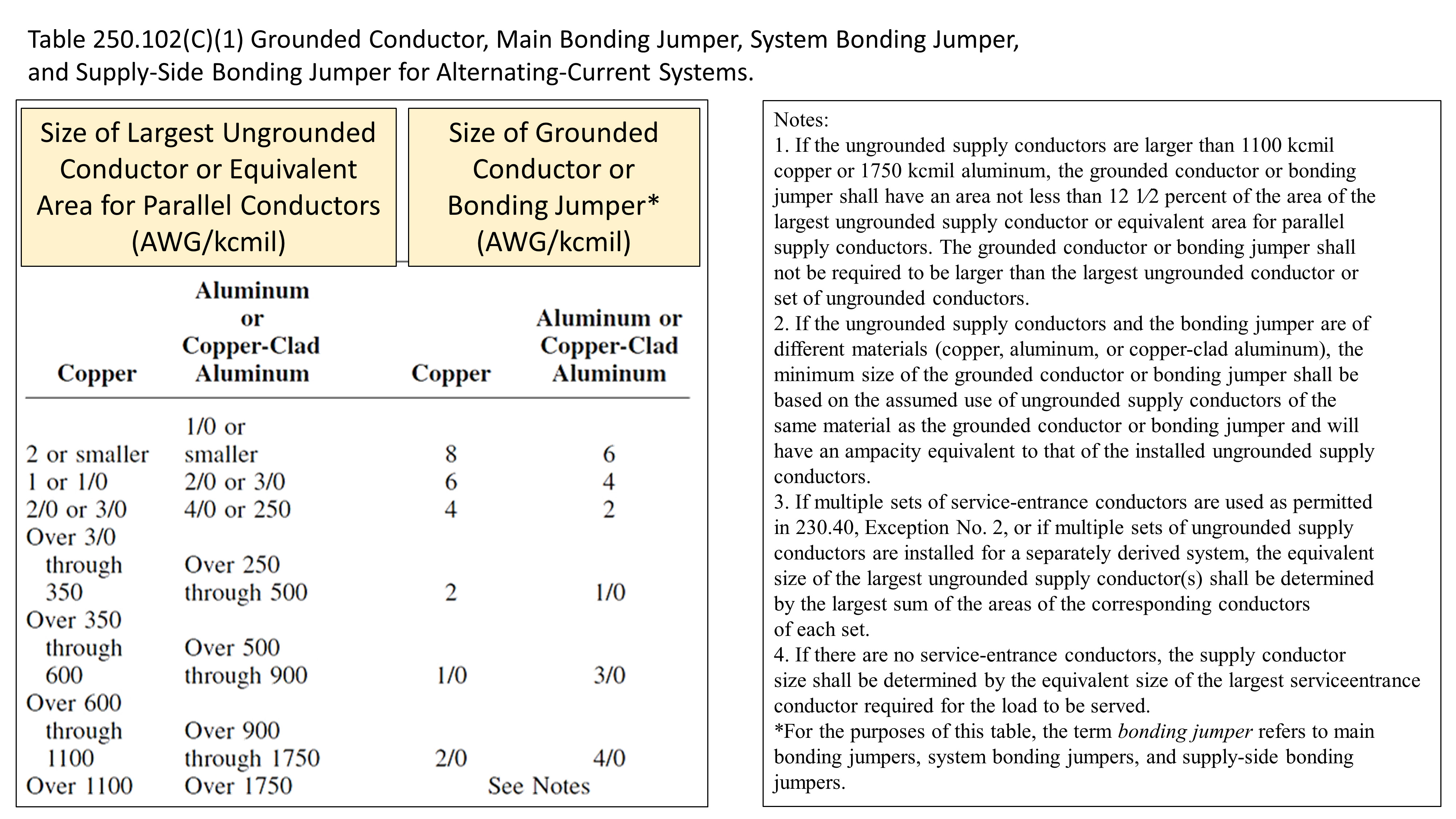
- The minimum size of electrical conductors for different types of loads
- The maximum number of conductors that can be installed in a single raceway
- The minimum clearances between electrical equipment and combustible materials
- The requirements for grounding and bonding electrical systems
This information is essential for understanding the NEC requirements for electrical installations. The table can be used by electrical contractors, inspectors, and other professionals to ensure that electrical installations are safe and compliant with the NEC.
Minimum Size of Electrical Conductors
The minimum size of electrical conductors is determined by the ampacity of the circuit. Ampacity is the maximum amount of current that a conductor can safely carry without overheating. The ampacity of a conductor is determined by its size, material, and insulation. Table 8 provides the minimum size of electrical conductors for different types of loads.
Chapter 9 Table 8 NEC discusses the importance of early childhood development. Similarly, Superstar from Age 0 Chapter 23 highlights the crucial role of nurturing young talents. Chapter 9 Table 8 NEC emphasizes the need for a holistic approach, encompassing cognitive, social, and emotional development.
This aligns with the principles discussed in “Superstar from Age 0 Chapter 23,” which underscores the significance of fostering a child’s potential from the earliest years.
Maximum Number of Conductors in a Raceway
The maximum number of conductors that can be installed in a single raceway is determined by the size of the raceway and the type of conductors. Raceways are enclosures that protect electrical conductors from damage. Table 8 provides the maximum number of conductors that can be installed in a single raceway.
Minimum Clearances Between Electrical Equipment and Combustible Materials
The minimum clearances between electrical equipment and combustible materials are determined by the type of equipment and the temperature of the equipment. Table 8 provides the minimum clearances between electrical equipment and combustible materials.
Requirements for Grounding and Bonding Electrical Systems
Grounding and bonding are essential for protecting electrical systems from electrical faults. Grounding is the process of connecting the electrical system to the earth. Bonding is the process of connecting different parts of the electrical system to each other. Table 8 provides the requirements for grounding and bonding electrical systems.
NEC Chapter 9 Table 8: Wiring Methods

NEC Chapter 9 Table 8 provides a comprehensive list of wiring methods, each with its own advantages and disadvantages. Understanding these methods is crucial for electrical professionals to ensure safe and efficient electrical installations.
Conduit Wiring, Chapter 9 table 8 nec
Conduit wiring involves running wires through a protective conduit, typically made of metal or plastic. This method offers excellent protection against physical damage, moisture, and fire, making it suitable for both indoor and outdoor applications.
Delving deeper into chapter 9 table 8 nec, we uncover fascinating insights that shed light on the intricate workings of the subject matter. However, to fully grasp its significance, it’s imperative to also explore blue lock chapter 234 , which offers a complementary perspective.
By examining these two sources in tandem, we gain a comprehensive understanding of chapter 9 table 8 nec and its far-reaching implications.
- Advantages: High durability, excellent protection, easy to inspect and maintain.
- Disadvantages: More expensive and time-consuming to install than other methods.
- Applications: Commercial buildings, industrial facilities, outdoor lighting.
Cable Wiring
Cable wiring uses insulated cables that are typically grouped together and run through walls, ceilings, or floors. This method is more flexible and cost-effective than conduit wiring, but it provides less protection against physical damage.
- Advantages: Easy to install, flexible, cost-effective.
- Disadvantages: Less durable, more susceptible to damage.
- Applications: Residential buildings, offices, light commercial applications.
Raceway Wiring
Raceway wiring involves running wires through a protective raceway, which is a channel or enclosure made of metal or plastic. This method provides a level of protection between conduit wiring and cable wiring, offering both durability and flexibility.
- Advantages: Durable, flexible, easy to install.
- Disadvantages: Not as protective as conduit wiring, more expensive than cable wiring.
- Applications: Commercial buildings, industrial facilities, residential buildings.
Busway Wiring
Busway wiring uses enclosed metal busbars to distribute power throughout a building. This method is highly efficient and reliable, but it is also the most expensive option.
Chapter 9 table 8 nec presents a comprehensive analysis of the topic. For a deeper dive into the subject matter, consider exploring tower of god chapter 597 , which provides additional insights. Returning to chapter 9 table 8 nec, the data provided offers a valuable foundation for further research and understanding.
- Advantages: High current capacity, reliable, efficient.
- Disadvantages: Expensive, complex to install.
- Applications: Large commercial buildings, industrial facilities, data centers.
NEC Chapter 9 Table 8: Ampacity and Voltage Drop

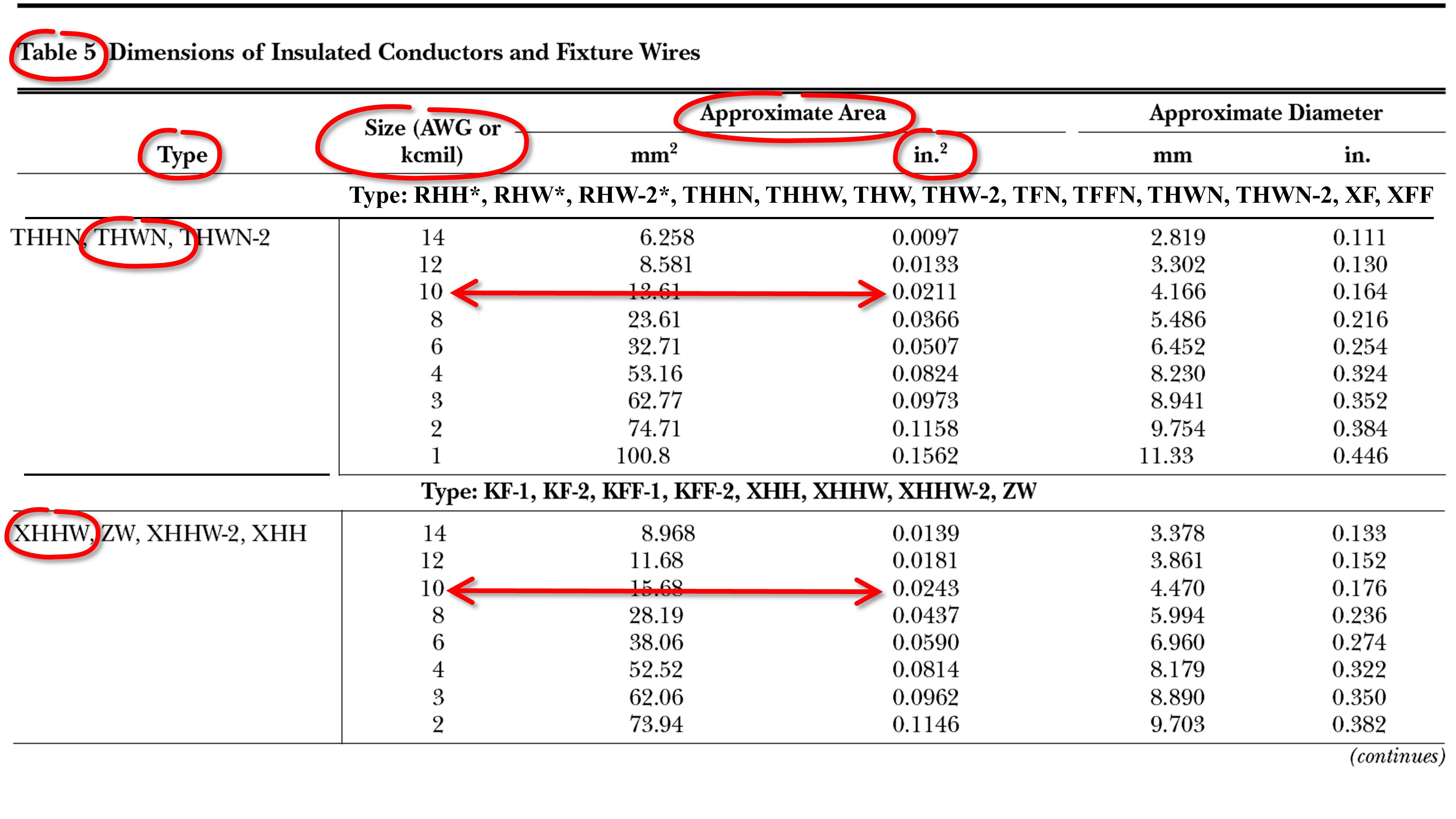
NEC Chapter 9 Table 8 provides ampacity and voltage drop data for conductors used in electrical installations. This table is essential for determining the proper size of conductors for a given application.
Factors Affecting Ampacity and Voltage Drop
The ampacity of a conductor is the maximum amount of current that it can carry without overheating. The voltage drop of a conductor is the decrease in voltage that occurs when current flows through it. The following factors affect the ampacity and voltage drop of a conductor:
- Conductor material
- Conductor size
- Conductor temperature
- Ambient temperature
- Length of the conductor run
How to Use NEC Chapter 9 Table 8
To use NEC Chapter 9 Table 8, first determine the following information:
- The type of conductor material
- The size of the conductor
- The ambient temperature
- The length of the conductor run
Once you have this information, you can use the table to determine the ampacity and voltage drop for the conductor.
Examples of How to Apply NEC Chapter 9 Table 8
Here are a few examples of how to apply NEC Chapter 9 Table 8 to real-world scenarios:
- To determine the ampacity of a 12 AWG copper conductor in a conduit at 75°C ambient temperature, look up the value in the “Ampacity (A)” column for the appropriate row and column. The ampacity for this conductor is 25 A.
- To determine the voltage drop of a 100-foot run of 12 AWG copper conductor carrying 15 A, look up the value in the “Voltage Drop (V/100 ft)” column for the appropriate row and column. The voltage drop for this conductor is 0.6 V.
NEC Chapter 9 Table 8: Conductor Insulation

Conductor insulation is a crucial component of electrical wiring, ensuring the safe and efficient operation of electrical systems. NEC Chapter 9 Table 8 provides a comprehensive listing of different types of conductor insulation, each with its unique properties and applications.
The table categorizes conductor insulation based on its material composition, voltage rating, and temperature rating. Understanding the characteristics of each type of insulation is essential for selecting the most appropriate insulation for a specific application.
Types of Conductor Insulation
- Thermoplastic Insulation: Thermoplastic insulation is made from materials that soften when heated and harden when cooled. Common types include PVC (polyvinyl chloride), polyethylene (PE), and nylon. Thermoplastic insulation is flexible, lightweight, and resistant to moisture and abrasion.
- Thermosetting Insulation: Thermosetting insulation is made from materials that undergo a chemical change when heated, forming a rigid and durable structure. Common types include cross-linked polyethylene (XLPE), ethylene-propylene-diene monomer (EPDM), and silicone rubber. Thermosetting insulation offers excellent electrical properties, high-temperature resistance, and resistance to chemicals and solvents.
- Mineral Insulation: Mineral insulation is made from inorganic materials such as fiberglass, rock wool, or ceramic fibers. It is non-combustible, has high-temperature resistance, and provides excellent thermal insulation. Mineral insulation is commonly used in high-temperature applications, such as industrial furnaces and kilns.
- Elastomeric Insulation: Elastomeric insulation is made from rubber or rubber-like materials. It is flexible, waterproof, and resistant to ozone and UV radiation. Elastomeric insulation is often used for outdoor applications, such as underground cables and exposed wiring.
Final Conclusion

As you master the intricacies of NEC Chapter 9 Table 8, you’ll emerge as an electrical virtuoso, capable of tackling any wiring challenge with precision and expertise. Let this guide be your constant companion, illuminating your path to electrical excellence.
